Configuring OSPF on Cisco Routers: Easy Step-by-Step Guide
Are you prepping for your CCNA or another networking certification exam and feeling a bit anxious about OSPF configuration? You're not alone. Open Shortest Path First (OSPF) is a fundamental topic in networking and one of the routing protocols you'll definitely encounter in your studies (Introduction to OSPF). It's worth mastering because OSPF is widely used in real-world networks for its efficiency and scalability. Unlike older protocols such as RIP, which share entire routing tables, OSPF shares link-state information (LSAs) so networks can converge faster (Configuring OSPF). In plain terms, OSPF helps routers find the best paths to destinations quickly and reliably – a must-have skill for any aspiring network engineer.
In this OSPF tutorial, we'll walk through a step-by-step OSPF configuration on a Cisco router – from starting the OSPF process to verifying it works. Think of it like a peer guiding you through a lab exercise. We'll use a hypothetical scenario (the kind you'd encounter in a CCNA OSPF setup lab) to make things relatable and fun. Along the way, I'll explain each Cisco IOS command and show sample CLI output, so you understand not just what to do, but why you're doing it. By the end of this guide, you should feel confident configuring OSPF on Cisco routers and be ready to tackle exam questions on it.
Lab Setup: Two Routers Running OSPF
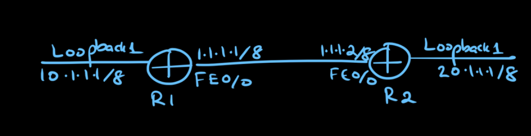
(OSPF Configuration Example 1: Adjacency Formation Between Two Cisco Routers - Tutorials) (image)Imagine a simple lab with two Cisco routers (R1 and R2) connected to each other, similar to what you might set up in a classroom. Our goal is to configure OSPF on both routers so they become neighbors (form an adjacency) and share routes. Each router also has a loopback interface representing a local LAN: for instance, R1 has a loopback with network 10.0.0.0/8 and R2 has one with network 20.0.0.0/8. The diagram above illustrates this setup: R1 and R2 are connected via their FastEthernet 0/0 interfaces (IP addresses 1.1.1.1 and 1.1.1.2 respectively), and each has a loopback interface (10.1.1.1 on R1, 20.1.1.1 on R2). By running OSPF, R1 should learn about the 20.0.0.0/8 network from R2, and R2 should learn about the 10.0.0.0/8 network from R1. Next, we'll go through the steps to make this happen!
Step 1: Prepare the Network
Before configuring OSPF, you need to have basic connectivity between your routers. Ensure that each router's interfaces have IP addresses and that the routers can ping each other on the connected link. In our example, we'd configure the FastEthernet0/0 interfaces and bring them up (no shutdown), as well as set up the loopback interfaces on R1 and R2 for the LAN networks.
R1(config)# interface FastEthernet0/0
R1(config-if)# ip address 1.1.1.1 255.0.0.0
R1(config-if)# no shutdown
R1(config-if)# exit
R1(config)# interface loopback0
R1(config-if)# ip address 10.1.1.1 255.0.0.0
R1(config-if)# exit

R2(config)# interface FastEthernet0/0
R2(config-if)# ip address 1.1.1.2 255.0.0.0
R2(config-if)# no shutdown
R2(config-if)# exit
R2(config)# interface loopback0
R2(config-if)# ip address 20.1.1.1 255.0.0.0
R2(config-if)# exit
(The above interface IP configuration is just an example for our scenario. You can use any IP addressing scheme as long as the routers have at least one common network between them. The loopback interfaces simulate extra networks to advertise.)
Step 2: Enable OSPF on the Router
Now let's enable OSPF on each router. In global configuration mode, use the router ospf <process-id> command to start the OSPF process (Implementing OSPFv2 Using network Commands > Implementing Basic OSPF Features | Cisco Press
). You can choose any number for the process ID (e.g., 1) – it's just an identifier for that router's OSPF instance and doesn't have to match the other router (Cisco OSPF Basic Configuration - FlackBox). We'll use process ID 1 on both R1 and R2 for simplicity. Once you enter this command, your prompt will change to (config-router)#, indicating you're now configuring the routing protocol (OSPF) on the router.
R1(config)# router ospf 1
R1(config-router)#    <--- You are now in OSPF config mode on R1
R2(config)# router ospf 1
R2(config-router)#    <--- OSPF config mode on R2
At this point, OSPF is enabled on the routers, but we haven't told it which networks to advertise or what interfaces to use. By default, no interfaces are active in OSPF yet. That's our next task.
Step 3: (Optional) Set the OSPF Router ID
This step isn't strictly required, but it's good practice: setting the router ID. The router ID is an identifier for the OSPF router, usually written as an IP address (not necessarily an actual interface IP). If you don't manually set it, IOS will pick one for you – it chooses the highest IP address among the router's interfaces (giving preference to loopbacks) (Implementing OSPFv2 Using network Commands > Implementing Basic OSPF Features | Cisco Press
). In a lab, it's helpful to set easy-to-read RIDs (for example, 1.1.1.1 for R1, 2.2.2.2 for R2) so you can recognize routers in OSPF outputs. To set the RID, use the router-id command in OSPF configuration mode:
R1(config-router)# router-id 1.1.1.1
R2(config-router)# router-id 2.2.2.2
After setting the router ID, if OSPF was already running, you might need to reset the OSPF process (using clear ip ospf process) for the change to take effect. Since we're just setting it up now, it will be used when OSPF forms its neighbor relationships. These RIDs will show up in various OSPF show commands as a way to identify the routers.
Step 4: Advertise Networks in OSPF (Define OSPF Areas)
With OSPF enabled and a router ID set, we need to tell OSPF which networks to advertise and what area they belong to. In OSPF configuration mode on each router, use one or more network <network-address> <wildcard-mask> area <area-id> statements. This command identifies a range of IP addresses (using a wildcard mask) and assigns those interfaces to a specific OSPF area (Implementing OSPFv2 Using network Commands > Implementing Basic OSPF Features | Cisco Press
) (OSPF Configuration Example 1: Adjacency Formation Between Two Cisco Routers - Tutorials). Basically, the router will compare the network address/mask you provide against its interface IPs; any interface that falls in that range gets OSPF enabled on it.
In our case, we'll put all networks in area 0 (the backbone area). We use a wildcard mask that is the inverse of the subnet mask. For example, for the 1.0.0.0/8 network, the subnet mask is 255.0.0.0, so the wildcard mask is 0.255.255.255. Here's what we configure:
R1(config-router)# network 1.0.0.0 0.255.255.255 area 0
R1(config-router)# network 10.0.0.0 0.255.255.255 area 0

R2(config-router)# network 1.0.0.0 0.255.255.255 area 0
R2(config-router)# network 20.0.0.0 0.255.255.255 area 0
On R1, the first command tells OSPF to include the FastEthernet0/0 interface (1.1.1.1/8 falls within 1.0.0.0/8) in area 0, and the second command includes the loopback0 (10.1.1.1 is in 10.0.0.0/8). On R2, we do the same for its FastEthernet0/0 (in 1.0.0.0/8) and loopback0 (in 20.0.0.0/8). The moment these network statements are entered on both routers, OSPF will start sending hello packets out the interfaces. R1 and R2 will see each other on the 1.0.0.0/8 link, realize they're both in area 0, and attempt to form an OSPF neighbor adjacency.
Step 5: Verify OSPF Neighbor Adjacency
After a few seconds, R1 and R2 should discover each other and form an OSPF neighbor relationship. We can verify this using the show ip ospf neighbor command on either router. For example, on R1:
R1# show ip ospf neighbor

Neighbor ID     Pri   State           Dead Time   Address       Interface
2.2.2.2           1   FULL/DR         00:00:33    1.1.1.2       FastEthernet0/0
Let's break down this output. The Neighbor ID 2.2.2.2 is the OSPF Router ID of R2. The Address 1.1.1.2 is R2's IP address on the link. The Interface is the local interface (R1's Fa0/0) through which R1 sees R2 (Implementing OSPFv2 Using network Commands > Implementing Basic OSPF Features | Cisco Press
). Most importantly, the State is FULL, meaning R1 and R2 have fully exchanged OSPF information and are now fully adjacent (i.e., they are OSPF neighbors) (Implementing OSPFv2 Using network Commands > Implementing Basic OSPF Features | Cisco Press
). The /DR indicates that R2 is the Designated Router on this network segment (and R1 would be the Backup DR), which is normal for a broadcast network with two routers. If you see FULL (or FULL/DR and FULL/BDR as in this case), your adjacency is up and running!
Step 6: Verify OSPF Routes in the Routing Table
Finally, let's confirm that each router has learned the other's network via OSPF. Use show ip route on R1 and R2. You should see routes marked with an O in the routing table, which denotes OSPF-learned routes (Implementing OSPFv2 Using network Commands > Implementing Basic OSPF Features | Cisco Press
). On R1, for instance, we expect to see R2's 20.0.0.0/8 network appear as an OSPF route:
R1# show ip route ospf
     O    20.0.0.0/8 [110/2] via 1.1.1.2, 00:00:07, FastEthernet0/0
     C    10.0.0.0/8 is directly connected, Loopback0
     C    1.0.0.0/8 is directly connected, FastEthernet0/0
In the above output, the line starting with O is the important one: it shows that 20.0.0.0/8 is learned via OSPF. The [110/2] indicates the route's administrative distance (110 for OSPF) and the cost metric (2 in this case). The route is learned via 1.1.1.2 (R2's address) out interface Fa0/0. This means R1's OSPF process has indeed learned about R2's network. Similarly, on R2 you would see an O route for 10.0.0.0/8 via 1.1.1.1. Whenever you see routes labeled with an 'O' in the routing table, you know OSPF is successfully exchanging network information (Implementing OSPFv2 Using network Commands > Implementing Basic OSPF Features | Cisco Press
).
Step 7: Troubleshooting OSPF (What if it doesn't work?)
Sometimes things don't go as planned. Imagine your friend is working on the same lab and says, "My OSPF configuration is not working; the routers aren't becoming neighbors." As a fellow student, here are a few troubleshooting tips you might suggest:
- Area mismatch: Ensure both routers configured the link in the same OSPF area. If R1's interface is in area 0 but R2's is in area 1, they will never form adjacency.
- Network statement oversight: Double-check that the
networkcommands on each router actually cover the interface IPs. A typo in the network address or wildcard mask could mean an interface isn't included in OSPF. - Interface issues: Verify the interfaces are up and can ping each other (no cable or VLAN issues in your lab). OSPF won't form neighbors if there's no basic IP connectivity.
- Passive interface: If an interface is set as passive in OSPF, the router will not send hello packets on it, preventing neighbor formation. (In our simple setup we didn't use
passive-interface, but it's a common setting in larger networks to suppress OSPF on LAN interfaces.) Make sure the interface between routers is not passive. - OSPF authentication: For more advanced setups, if OSPF authentication is enabled on one side and not the other (or passwords don't match), neighbors won't form. This likely isn't the case in a basic CCNA lab unless explicitly configured.
Essential OSPF Show Commands for Verification and Troubleshooting
Now that you've configured OSPF on your Cisco routers, you'll need to verify and troubleshoot your setup. Here are the most valuable Cisco IOS show commands every networking student should know when working with OSPF.
1. Verify OSPF Neighbors
Check neighbor adjacencies and their states. This helps you confirm that routers are successfully communicating.
Router# show ip ospf neighbor
- FULL state: Good! Routers have fully exchanged OSPF information.
- INIT or 2-WAY: Potential issue. Routers see each other but haven't completed adjacency.
- No output: Check connectivity and OSPF configuration (area mismatches, passive interfaces, etc.).
2. Check OSPF Routing Table Entries
View all OSPF-learned routes in your router's routing table.
Router# show ip route ospf
Look for:
- Routes marked with
O—these indicate successfully learned OSPF routes. - Correct next-hop IP addresses and exit interfaces.
3. Inspect OSPF Interfaces
Check the status and configuration details of interfaces participating in OSPF.
Router# show ip ospf interface brief
Verify:
- Interfaces are correctly enabled for OSPF.
- Correct OSPF areas and interface states (e.g., DR/BDR on multi-access networks).
4. Detailed OSPF Interface Information
Get in-depth details about OSPF interfaces, timers, hello/dead intervals, and authentication settings.
Router# show ip ospf interface [interface]
Use this command to troubleshoot hello/dead timer mismatches, MTU mismatches, or authentication issues.
5. OSPF Process Information and Router ID
Display router ID, areas, SPF statistics, and general OSPF configuration.
Router# show ip protocols
Check:
- Correct OSPF process ID.
- Accurate router ID.
- Networks advertised by OSPF.
Quick Troubleshooting Tips Using These Commands:
| Problem | Possible Cause | Recommended Command(s) |
|---|---|---|
| No neighbors forming | Area mismatch, passive interfaces, or connectivity issues | show ip ospf neighbor, show ip ospf interface brief |
| Missing OSPF routes | Network statements incorrect or adjacency incomplete | show ip route ospf, show ip protocols |
| Adjacency stuck in INIT or 2-WAY | DR election issue or misconfigured timers | show ip ospf interface [interface], show ip ospf neighbor |
These commands will become your go-to tools, helping you verify your OSPF configurations quickly and troubleshoot efficiently, making your exam preparation smoother and more confident.
By systematically checking these factors, you'll usually pinpoint the issue. In a classroom setting, troubleshooting OSPF can be a great learning exercise – it reinforces understanding of how OSPF works under the hood!
Summary of Key OSPF Configuration Commands
The following table summarizes some of the key commands used when configuring OSPF on a Cisco router and what they do:
| Command | Purpose |
|---|---|
router ospf <process-id> |
Enable OSPF on the router and enter OSPF configuration mode (using the specified process ID, which is locally significant). |
router-id <A.B.C.D> |
Manually set the OSPF Router ID to the given value (in the format of an IP address). Useful for identification. |
network <net> <wildcard> area <area> |
Advertise a network in OSPF. All interfaces with IP addresses matching <net> (with the wildcard mask) will be included in the OSPF process under the specified area. |
passive-interface <interface> |
Make an interface passive. OSPF will still advertise that network to other routers, but it will not form adjacencies or send hellos on that interface (good for LAN interfaces with no other routers). |
As you prepare for your CCNA or other networking exams, remember to practice OSPF configuration in lab environments (like Packet Tracer or real gear) – it will reinforce your understanding. You can experiment with additional scenarios too: try adding a third router, or configuring multiple OSPF areas (to explore OSPF inter-area behavior), or enabling OSPF authentication for security. Each of these will build on the foundation you've established here.
In the world of networking, OSPF is a powerful tool. With the knowledge you've gained, you're well on your way to mastering it. Happy networking, and good luck on your certification journey!